
Home › Solid carbide drills › Micro drilling
Application guide
Carbide micro drilling for CNC machining
For CNC micro drilling, identify the material, hole diameter and depth before choosing a catalogue family. Check the flute length and shank for that size, and specify whether the application requires internal coolant.
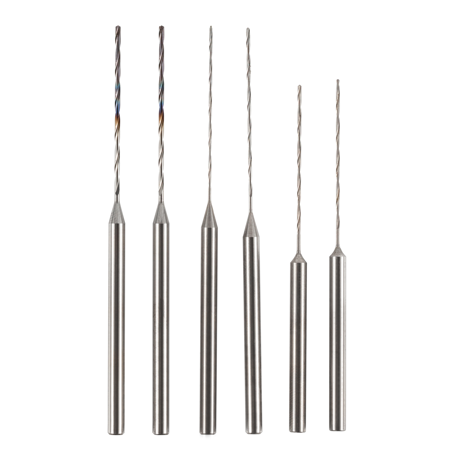
Separate the tool families before choosing a size
Standard micro drills
The catalogue separates 3-shank and 4-shank micro drills. Both list aluminum and steel geometries; include the actual material grade when requesting a tool.
Standard coolant drills
The 4-Shank Coolant Drill is a separate series with internal coolant. Its listed diameter range starts at Φ2.00 mm.
Custom micro through-coolant
Micro through-coolant and other non-standard geometries are reviewed against the application. Send the diameter, depth and coolant requirements rather than assuming a standard combination.
Check diameter, flute length and shank together
The three families below have different flute lengths and coolant configurations. Read the dimensions as a set, rather than selecting on diameter alone.
| Catalogue family | Diameter (mm) | Flute length (mm) | Shank / OAL (mm) |
|---|---|---|---|
| 3-Shank Micro Drill | Φ0.10–3.00 | 1–10 | 3 / 38 |
| 4-Shank Micro Drill | Φ2.00–4.00 | 10–20 | 4 / 50 |
| 4-Shank Coolant Drill | Φ2.00–4.00 | 20 or 28 | 4 / 60 or 66 |
For example, the Φ0.10–Φ0.29 band in the 3-Shank Micro Drill table lists a 1 mm flute length, 3 mm shank and 38 mm overall length. Other bands use different flute lengths. See page 5 of the specifications for each pairing.
Listed diameter bands do not establish every available ordering increment. Confirm the required diameter and geometry before selecting the tool.
Prepare the small-hole enquiry
- Material grade and hardness, hole diameter, depth and blind or through condition.
- Entry and exit geometry, cross-holes, and the part drawing where available.
- Hole tolerance, surface finish and permitted burr condition.
- Machine and spindle, holder, tool reach and available coolant equipment.
- Batch quantity, current tooling and the issue the new tool needs to address.
For a geometry outside the standard table, use the custom tooling enquiry route. Cutting conditions are reviewed for the actual setup.
Send the small-hole requirements
Include the material, diameter, depth and machine conditions. A drawing helps distinguish the standard options from a custom requirement.